Specifications are useful. Measurements are better. This page documents how the Rephiro Bioharmonizer should be tested on the bench — carrier, sweep, pulsing, waveform, voltage, current and spectrum — and separates published specifications from values that have actually been measured.
Rephiro is specified as a contact-based frequency device using an approximately 3.1 MHz carrier, a 0.1–150 kHz automatic sweep and approximately 14 Hz pulsing. Those are product specifications. This article does not invent oscilloscope results: all bench values remain marked as pending until they are measured under a documented test setup.
For the broader technology context, start with the Complete Guide to Rife Machines →
The goal is not to create a dramatic oscilloscope screenshot. The goal is to document the device, instruments, probe configuration, load, settings and raw output so another technically competent person can understand what was measured.
Why publish a technical test at all?
Frequency products are often marketed with long lists of numbers but surprisingly little measurement data. A technical buyer may reasonably ask whether the carrier is present, whether the sweep covers the stated range, what waveform is produced, how the output behaves under load, whether the ~14 Hz timing layer is visible and whether the signal is repeatable.
Those are measurable questions.
Important: a technical signal test verifies electronics. It does not prove a therapeutic or medical effect.
Published specification vs measured result
This page follows a strict rule: if a value has not yet been measured on the bench, it is labelled as a specification or pending result.
| Parameter | Published specification | Bench result | Status |
|---|---|---|---|
| Carrier frequency | ~3.1 MHz | Pending | Pending |
| Lower-frequency sweep | ~0.1–150 kHz | Pending | Pending |
| Pulsing / gating | ~14 Hz | Pending | Pending |
| Waveform shape | Not fully characterized publicly | Pending oscilloscope capture | Pending |
| Output voltage/current | No bench value published here | Pending under defined load | Pending |
| Active/rest cycle | ~5.5 min / ~2 min | Pending timed verification | Pending |
What equipment is needed?
Oscilloscope
Enough bandwidth and sample rate to characterize the ~3.1 MHz carrier, lower-frequency sweep and timing structure.
Spectrum analyzer / FFT
Shows carrier, harmonics, modulation products and sidebands in the frequency domain.
True-RMS meter / DMM
Useful for selected voltage and resistance checks, but not sufficient by itself for MHz modulation.
Also document probe type, attenuation, test leads, load resistors, instrument models, firmware/calibration status and measurement date.
Why test under a defined load?
A contact-frequency device does not normally operate into an infinite impedance. Human skin and tissue are complex, nonlinear and frequency-dependent, so a resistor cannot perfectly reproduce a person. But a defined load gives something equally important: repeatability.
Measure unloaded only if appropriate, then repeat under one or more documented resistive loads. Publish the actual resistor values rather than describing them vaguely as a "body simulation."
Test 1 — Is the ~3.1 MHz carrier really present?
Objective
Verify the high-frequency carrier and measure its actual frequency and stability.
Method
Connect the output through the documented test setup, use sufficient oscilloscope bandwidth and capture several carrier cycles clearly.
Record
Frequency, peak-to-peak amplitude, waveform shape, probe setting, oscilloscope bandwidth, timebase and test load.
Test 2 — Does the sweep really cover 0.1 to 150 kHz?
The key questions are the actual start and end frequency, sweep duration, whether it is linear/logarithmic/stepped, whether it sweeps continuously, and how repeatable the timing is.
Test 3 — What does the ~14 Hz pulsing actually look like?
The output could be fully switched, amplitude-gated, burst-modulated or periodically reduced. A long timebase should show the implementation.
Measure repetition rate, on-time, off-time, duty cycle and gating depth rather than simply naming every visible envelope "14 Hz."
Test 4 — What is the waveform?
Frequency alone does not describe a signal. Capture the output at three time scales.
Carrier scale
Zoom into individual MHz cycles.
Modulation scale
Show how the carrier envelope changes during the sweep.
Pulse scale
Show ~14 Hz gating and longer session timing.
Test 5 — Carrier, harmonics and sidebands
A frequency-domain capture can reveal signal structure that is difficult to see in the time domain. If the carrier is modulated, sidebands may appear around it. Measure first and interpret second.
For the underlying signal-processing physics, see How the Hoyland Sideband Method Works →
Tests 6 & 7 — Voltage and current under load
Voltage should never be reported without measurement conditions. Record peak-to-peak voltage, RMS voltage if meaningful for the waveform, load resistance, bandwidth and probe ratio.
Current can be measured directly with a suitable setup or derived from voltage across a known resistor. The final article should publish the measurement method alongside the number.
| Load | Voltage | Current | Notes |
|---|---|---|---|
| Load A | Pending | Pending | Pending |
| Load B | Pending | Pending | Pending |
| Load C | Pending | Pending | Pending |
Test 8 — Verify the 5.5-minute active / 2-minute rest cycle
This can be verified with a long acquisition, logger or timed output measurement.
Test 9 — Power consumption
The current Rephiro specification is approximately 3 W. A suitable power meter can verify idle consumption, active consumption, rest-cycle consumption and variation during operation. Input power is not the same thing as output signal power, so report it as a separate measurement.
Test 10 — Is the output repeatable?
Run at least three independent sessions and compare carrier frequency, sweep start/end, sweep timing, ~14 Hz pulse rate, amplitude under the same load and active/rest timing.
Testing multiple randomly selected production units is more informative than publishing one perfect screenshot from a specially selected sample.
What Phipower should publish with the final results
- instrument make/model;
- oscilloscope bandwidth and sample rate;
- probe type and attenuation;
- test-load values;
- connection diagram;
- high-resolution oscilloscope screenshots;
- spectrum screenshots;
- measurement date;
- serial/batch identifier of tested unit;
- raw CSV traces where available.
This creates original first-party content competitors cannot simply reproduce from the same public sources.
Recommended final results table
| Measurement | Specified | Measured | Deviation | Condition |
|---|---|---|---|---|
| Carrier | ~3.1 MHz | Pending | Pending | Defined load |
| Sweep minimum | ~0.1 kHz | Pending | Pending | Defined load |
| Sweep maximum | ~150 kHz | Pending | Pending | Defined load |
| Pulse rate | ~14 Hz | Pending | Pending | Defined load |
| Active/rest | ~5.5 / 2 min | Pending | Pending | Timed output |
| Voltage/current | — | Pending | — | Report load |
| Power consumption | ~3 W | Pending | Pending | Input power |
What would a successful technical test prove?
If the measurements match the specification, the test can support statements about carrier frequency, sweep range, timing, waveform, spectrum and repeatability.
It would not prove that specific pathogens are destroyed, that historical MOR claims are correct or that Rephiro treats a disease.
Electronics evidence and clinical evidence answer different questions. Good product research should keep them separate.
Current Rephiro specification snapshot
| Specification | Current value |
|---|---|
| Carrier | ~3.1 MHz |
| Automatic sweep | ~0.1–150 kHz |
| Pulsing | ~14 Hz |
| Session cycle | ~5.5 min active / ~2 min rest |
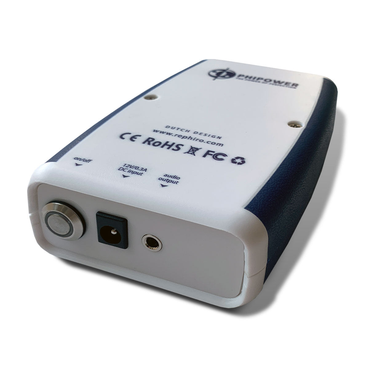
| Input architecture | 5 V USB to 12 V DC |
| Power | ~3 W |
| Dimensions | ~11.5 × 7.5 × 3 cm |
| Weight | ~105 g |
| Delivery | Contact accessories |
| Warranty | 1 year |
Frequently asked questions
The bottom line
The strongest Rephiro technical article is not "trust us — these are the frequencies." It is:
instrument → connection → load → waveform → spectrum → result.
~3.1 MHz carrier, 0.1–150 kHz sweep and ~14 Hz pulsing are current device specifications. Bench-verified values remain pending and should be added only after measurement.
Once those data are available, this can become one of the strongest original authority assets in the Phipower Rife cluster.
Rife Machine: The Complete Guide to Rife Frequencies, Technology & Devices →
This page documents product specifications and a proposed measurement protocol. It does not claim that pending bench measurements have already been performed. Electrical measurements verify signal characteristics only and do not establish medical efficacy. Rephiro is a wellness and lifestyle product, not a medical device.